
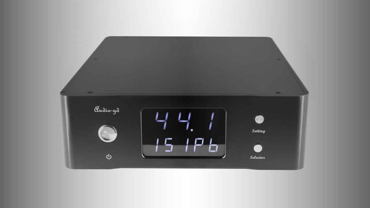
Audio-GD has announced the DI-24, a standalone digital interface intended to sit between a computer or compatible USB source and an external DAC. Rather than adding conversion itself, this component receives USB audio, processes and re-clocks the digital data, then offers several outputs for connection to a DAC: I2S over HDMI, coaxial S/PDIF and balanced AES/EBU.
The DI-24’s most distinctive provision is its 10MHz clock infrastructure. It includes internal Accusilicon 90/98MHz clock generators and a built-in 10MHz clock generator, but can also be used with an external reference clock or act as a reference source for another component. That makes it a more specialised proposition than a conventional USB-to-S/PDIF converter: it is aimed at systems where the DAC, digital transport and master-clock arrangement are considered as a whole.
Audio-GD has not stated a price, availability date or supported streaming services for the DI-24. It is a digital interface rather than a network streamer, so music playback software and network functionality will remain the responsibility of the connected computer or source.
What a digital interface does in a DAC-based system
A digital interface, sometimes called a digital-to-digital converter or DDC, does not convert digital music into analogue audio. Its job is to accept one digital connection format—here, USB—and output a format that may be more suitable for the DAC. This can be useful where a DAC’s USB implementation is less capable than its AES/EBU, coaxial or I2S input, or where a system owner needs clock synchronisation facilities unavailable from a typical computer connection.
The practical signal path is therefore USB source to DI-24, then DI-24 to DAC, followed by the usual DAC-to-amplifier analogue connection. The interface’s quality and compatibility matter because the data must arrive at the DAC correctly and with stable timing, while electrical noise from a computer’s USB subsystem must be prevented from unnecessarily reaching sensitive downstream circuitry.
Audio-GD bases the USB side on an Amanero Combo 384 module. Amanero’s USB audio modules are widely used in specialist digital audio products, though the important point for an owner is the stated platform compatibility: Windows, macOS, iOS and Linux are listed, with Audio-GD also reporting testing with selected Android TVs and smartphones. The specification table refers to “ISO”, presumably reflecting the supplied listing; prospective buyers using iOS should confirm their intended device and connection arrangement before purchase.

FPGA processing, clocking and electrical isolation
At the heart of the DI-24 is an Altera FPGA (field-programmable gate array). An FPGA is a configurable logic device: in digital audio hardware, it can be programmed to handle data routing, formatting and timing-related tasks rather than relying exclusively on a fixed-function receiver chip. Audio-GD says the FPGA generates the output signal and can operate in parallel or serial data-processing modes.
The manufacturer also says that the high-frequency FPGA IC is isolated from the USB interface, with the stated aim of reducing spurious noise during signal conversion and protecting clock accuracy. This distinction is worth making. Digital audio data are generally robust when transferred within specification, but the interface joining a noisy general-purpose computer to a DAC can also carry unwanted high-frequency electrical activity and ground-related noise. Isolation is intended to interrupt or reduce that unwanted path; its benefit in an individual system will depend on the connected source, DAC and grounding arrangement.
Internal clocks and the 10MHz reference option
The DI-24 uses a pair of Accusilicon 90/98MHz clock generators and includes a 10MHz clock generator. Audio-GD describes three clocking arrangements: using the DI-24’s internal clocks, operating from an external clock in slave mode, or sending its internal clock to a third-party device in master mode.
In digital audio, a clock establishes the timing reference used to move samples through the circuit. Timing uncertainty is commonly described as jitter; phase noise is a related way of characterising short-term clock instability. Audio-GD says its FPGA reduces jitter and phase noise, but it has not supplied measured figures, so no numerical comparison with other interfaces can be drawn from the announcement.
The inclusion of 10MHz input and output connections is chiefly relevant to owners of DACs or dedicated master clocks that accept a 10MHz reference. This is not the same as the audio sampling frequency—10MHz is a high-stability reference from which a component can derive its own operational clocks. A shared reference can be useful in a carefully specified multi-box digital system, but it is not a universal upgrade. The external component must support the same clock-reference arrangement, correct impedance and suitable input level.
The DI-24 provides separate 50-ohm and 75-ohm 10MHz BNC sync inputs, each specified for 0.3Vpp to 3Vpp, plus a 50-ohm 10MHz BNC sync output rated at more than 9dBm. Front-panel buttons select internal or external clock operation for the clock outputs. Correct cable impedance is important here: a 50-ohm clock input should be used with 50-ohm cable and termination, while the 75-ohm input requires a 75-ohm arrangement. Mixing them can compromise signal integrity.
Connections: I2S, AES/EBU and coaxial outputs
The DI-24’s output section gives it broad scope as a USB front end for an existing DAC. Its I2S output uses an HDMI-style connector carrying LVDS at 3.3V and 100 ohms. I2S separates audio data and clock signals, unlike S/PDIF and AES/EBU, which encode clocking with the digital audio stream. In principle, that can offer a direct interface between matched products.
However, HDMI is only the physical connector in this case; I2S-over-HDMI pin assignments are not universally standardised between brands. A DAC with an HDMI-shaped I2S socket is not automatically compatible. Audio-GD does not provide the pinout in the supplied information, so anyone considering the I2S route should obtain confirmation that the DI-24’s LVDS mapping matches their DAC before connecting it.
For more broadly standardised DAC connections, there is a coaxial S/PDIF output specified at 0.5Vp-p and 75 ohms, and an AES/EBU output specified at 5Vp-p and 110 ohms. AES/EBU uses a balanced connection and is often the natural choice where the DAC supports it and a properly specified 110-ohm AES cable can be used. Coaxial S/PDIF is the familiar 75-ohm single-ended alternative. Both are specified to support PCM up to 384kHz, while DSD support is stated for USB and I2S.
The DI-24 supports PCM to 32-bit/384kHz and DSD up to DSD512 over USB and I2S. PCM is the format used by most CD-quality and high-resolution downloads and streams, while DSD is a one-bit, very high sample-rate format found in some download libraries. The important limitation is interface-dependent: users with DSD material will need to use the I2S output if they want to retain the DI-24’s stated DSD capability, assuming their DAC’s I2S implementation is confirmed compatible. Audio-GD does not state whether DSD is carried natively or packaged in another transport format on each connection, so that should also be verified for a particular DAC.

Power-supply architecture and physical design
Audio-GD places considerable emphasis on power distribution. The DI-24 uses an R-core transformer and 13 separate power-supply groups for its different circuits. It further states that the USB interface, FPGA and clock sections are supplied by four groups of DC power supplies and five groups of ultra-fast linear power supplies, while all output circuits are powered by Class A supplies.
The terminology needs some context. A Class A amplifier normally means an output stage that remains continuously conducting, but in this case Audio-GD is describing the regulation and supply circuitry rather than a loudspeaker power amplifier. The stated regenerative supply uses Class A power supplies and Class A balanced amplifiers. The intended engineering rationale is to maintain low-noise, stable local power for circuits with differing demands—high-speed logic, clock generation and output drivers—rather than allowing one section’s switching activity to modulate another section’s supply rail.
Whether this architecture proves advantageous in a particular installation cannot be established without independent measurements or listening assessment. It does, however, explain why the DI-24 is a substantial mains-powered unit rather than a small USB-powered adapter. It consumes 17W, measures 360 x 240 x 85mm and weighs 3.5kg. Buyers should allow appropriate rack or shelf space and a sensible route for the USB, digital and, if used, BNC clock cables.
Setup considerations and likely audience
The DI-24 is most relevant to two kinds of user. The first is a DAC owner who wants to run a computer or compatible mobile source over USB but prefers the DAC’s AES/EBU, coaxial or I2S input. The second is a more advanced digital-system builder with a 10MHz-capable DAC, external master clock, or both. In either case, the component’s value depends on the rest of the system: a DAC with only USB input cannot use the DI-24’s output stage, and a DAC without clock-reference facilities will not make use of its 10MHz functions.
For a straightforward installation, USB-B from source to DI-24 and AES/EBU or coaxial from DI-24 to DAC is likely to be the least compatibility-sensitive route. Use a true 75-ohm cable for coaxial S/PDIF and a 110-ohm cable for AES/EBU where possible. I2S should be treated as a DAC-specific option, not simply an alternative HDMI lead connection.
The front-panel display shows PCM and DSD sample rates and is also used to view and select parameters. That is useful operational feedback when diagnosing source settings or confirming that a DAC is receiving the expected format. Audio-GD also provides a USB firmware-update button and an FPGA firmware-update connector. Firmware provision can be valuable where compatibility or processing functions need revision, although the supplied information does not specify the update procedure, software availability or policy.
As specified, the DI-24 is designed for 220–240V AC, 50/60Hz mains and is finished in black. Those in 100–120V regions should not assume compatibility without checking for a region-specific version. The supplied details do not list a remote control, network connection, Bluetooth or analogue outputs—appropriately, given that this is a focused digital interface rather than an all-in-one digital hub.
Audio-GD DI-24 key specifications
- Product type: Digital interface
- USB input: 1 x USB-B
- Clock inputs: 1 x 10MHz BNC, 50 ohms, 0.3Vpp–3Vpp; 1 x 10MHz BNC, 75 ohms, 0.3Vpp–3Vpp
- Digital outputs: I2S HDMI LVDS, 3.3V at 100 ohms; coaxial, 0.5Vp-p at 75 ohms; AES/EBU, 5Vp-p at 110 ohms
- Clock output: 10MHz BNC, more than 9dBm at 50 ohms
- Supported formats: USB/I2S PCM to 32-bit/384kHz and DSD to DSD512; AES/EBU/S/PDIF PCM to 384kHz
- System compatibility: Windows, macOS, iOS and Linux listed; selected Android TVs and smartphones tested by Audio-GD
- Mains requirement: 220–240V AC, 50/60Hz
- Power consumption: 17W
- Dimensions: 360 x 240 x 85mm
- Weight: 3.5kg
- Finish: Black
The DI-24’s appeal is therefore not its breadth of consumer-friendly features but the seriousness of its digital infrastructure: isolated USB input, FPGA-based output generation, multiple output standards, extensive separate regulation and configurable 10MHz clock operation. For a conventional DAC system, its strongest practical case is as a flexible USB-to-AES/EBU, coaxial or confirmed-compatible I2S bridge. For the narrower audience building a synchronised external-clock system, its 50-ohm and 75-ohm reference inputs and 10MHz output are the headline features to investigate.